Now we'll turn our attention to the remaining bits and bobs - wheels, propellers and cockpit.
| 01 Check ignore Backfacing. In the Top viewport select the middle three vertices for the fourth and fifth row of vertices down from the propellers (you should have six vertices selected in total). In the Soft Selection rollout turn on 'Use Soft Selection'and set the iallott to 0.25. Now move these vertices up in the Left viewport until they roughly match the background. | 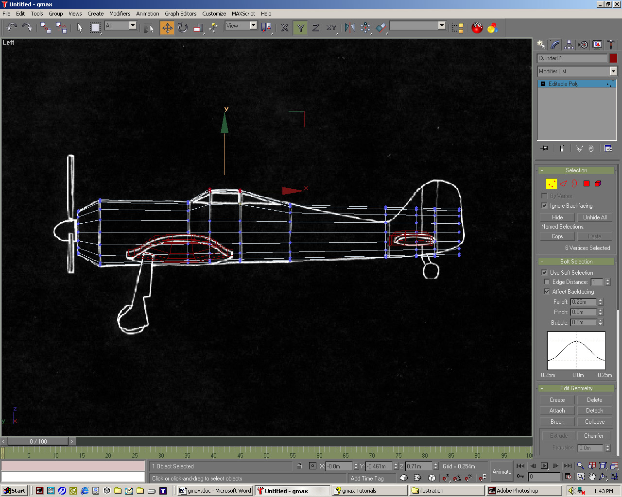 |
| 02 Turn Soft Selection and Ignore Backfacing off. In the Left viewport select the seventh column of vertices. Use Non-Uniform scale and Move in the y-axis to appropriately size this section. Repeat for the remaining columns of vertices, using Rotate on the final column to place this according to the background image. Next we'll make the central propeller housing | 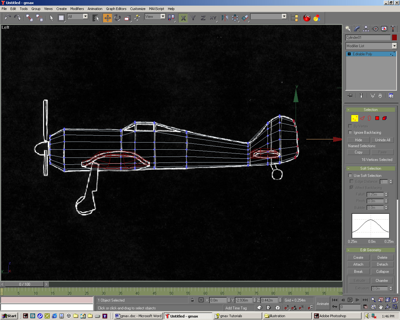 |
| 03 Create a sphere in the Front viewport, of 12 sides. Enter 0.5 in the Hemisphere field. Position this over this same element in the backgrounds, using Non-Uniform Scale to stretch it along its length to match the background. Rename it propeller-housing. For the first propeller create a box in the Front viewport. Centre this on the vertical propeller in the background image. | 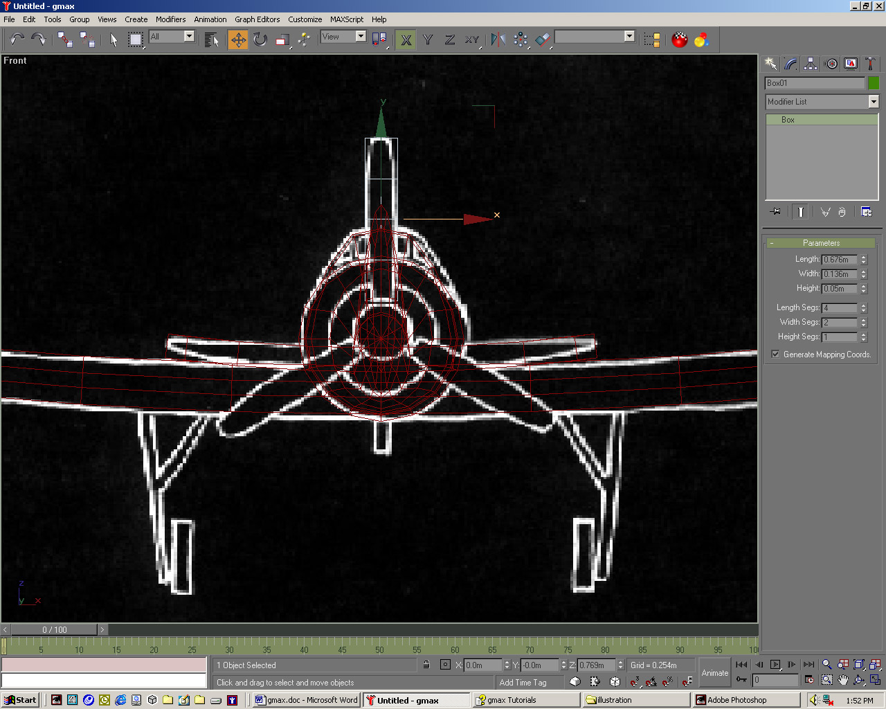 |
| 04 Give this 4 Length segments, 2 Width and 1 Height. Add a taper modifier acting in the y-axis with its Effect along the x of around -0.7 until it looks right. Add a Twist modifier of around 5 in the x-axis and move its centre to the bottom of the blade. Rename this propeller0l. Move the propeller's pivot point by clicking'Affect Pivot Point Only' in the Hierarchy panel.
|
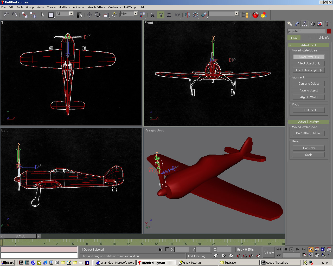 |
| 05 Select Align in the main toolbar then click the propeller-housing object. In the dialogue check the Z Position box and with both Current and Target Object set to Centre, click OK. Click 'Affect Pivot Point Only' again to leave this mode. Press the Array button to the left of Align. Enter 120 in the Incremental Z Rotate field and check the Instance button at the bottom-left. | 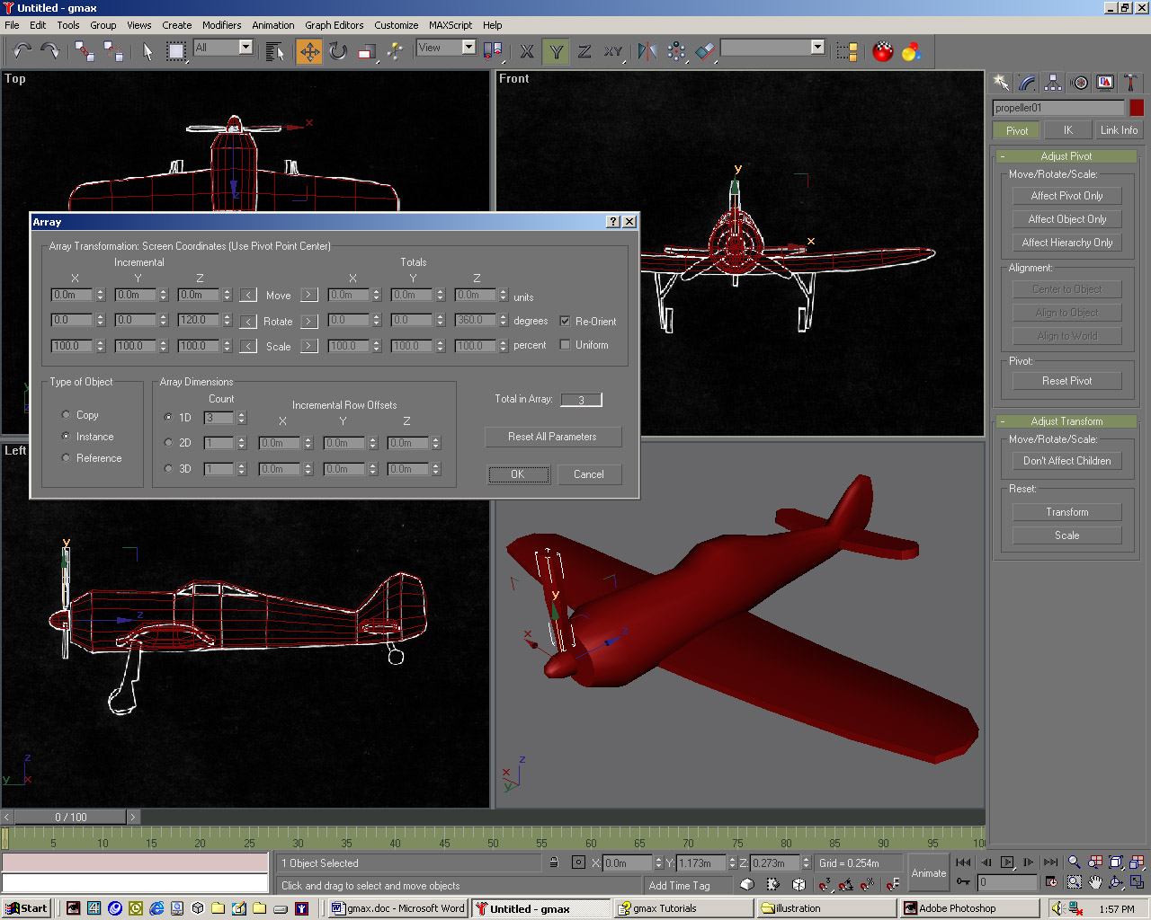 |
| 06 Enter 3 in the 1D Count, click OK. Press [H] to bring up 6 the Select Objects dialog and select the three propellers. Click Select and Link in the main toolbar. With the cursor over any propeller, drag to the central housing and release to link the objects, then right-click and pick Move. Create a cylinder for one of the front wheels and mirror an Instance for the other wheel.
|
 |
| 07 Use a box converted to Editable Polys to construct the first diagonal support for the wheels. At Polygon Sub-Object level select a polygon an the inside. In the Edit Geometry rollout increase the Extrude spinner and move this polygon to model the diagonal strut. Create the rear wheel from another cylinder, using Extrude on one of its polygons to form its support. | 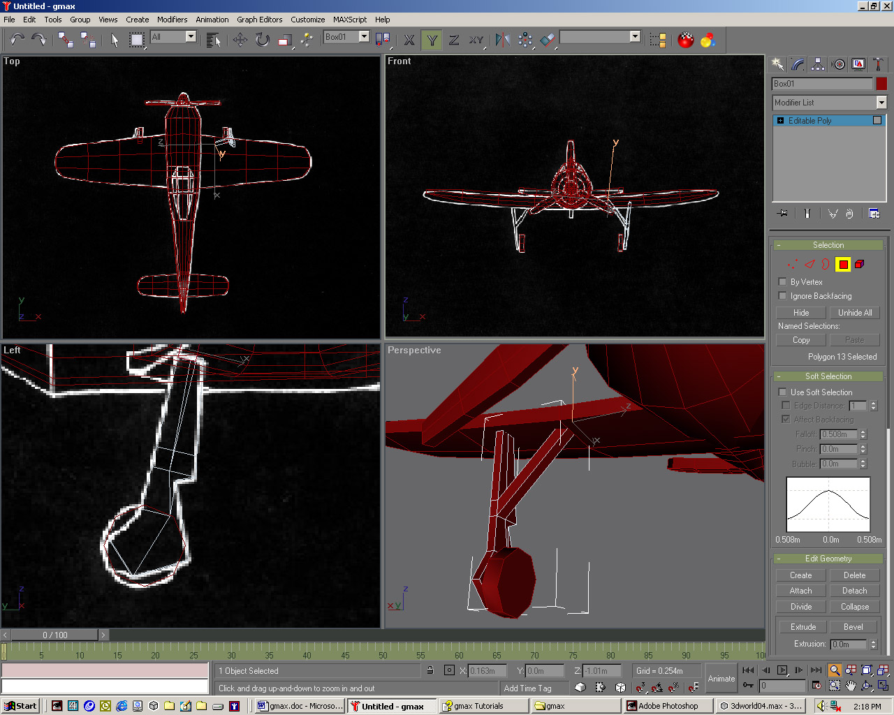 |
| 08 With the fuselage selected, go into Edge Sub-Object mode and turn on Ignore Backfacing. Turn on 30 Snap and set the options to Vertex. On the Edit Geometry rollout turn on Cut. Cut diagonal edges at front and rear of the cockpit in the Top viewport as shown above. Click to start the cut, click again for the second cut point and right-click to end the operation. | 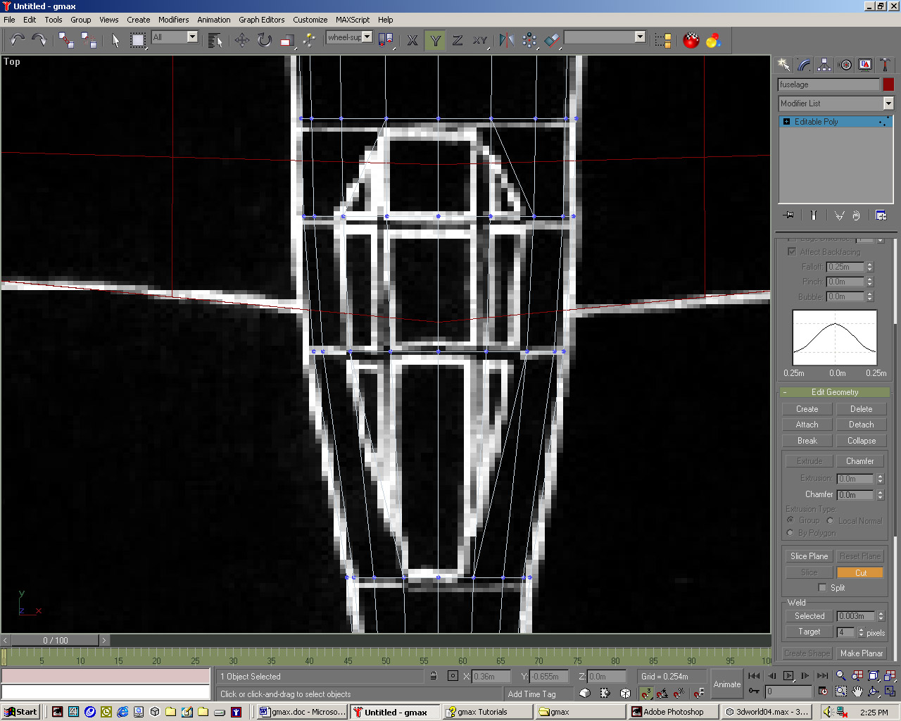 |
| 09 Select the edges that will form the frame of the windscreen, as shown in the screenshot above. In the Edit Geometry rollout, increase the Chamfer spinner by a tiny amount (around 0.91 m should work) to form the frame of the windscreen. Save your work so far as fokker2.gmax, and prepare to add the finishing touches to your creation. | 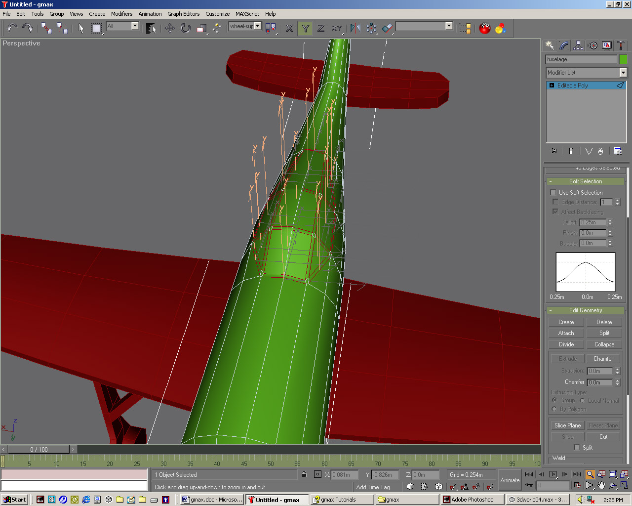 |